Learn to Make NES Games
Color in Motion
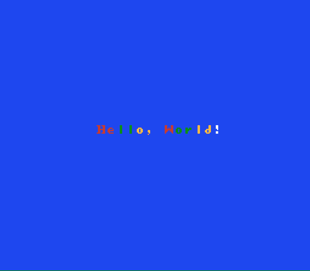
Our goal for this lesson is to expand our knowledge of the PPU to spice up our “Hello, World!” ROM into something a bit more exciting. To see it in action, load the finished product in your NES emulator of choice. You should see something like this:
Keeping Organized
The first thing you might notice about our code is that we have a few new files.
To make our code more readable, there are now a bunch of useful #defines for memory addresses and other constants in nes.h.
This will prevent us from having to do the math in our heads—when setting PPU_CTRL, for example, we can just or (|) together the flags we want to set.
A few of these constants (e.g. framerate) will differ between NTSC and PAL PPUs, so we’ll have to define either TV_NTSC or TV_PAL, e.g.:
#define TV_NTSC 1
#include "nes.h"
We’ve also created data.h to define things like palette data to keep our main source file cleaner and reset.h to include some new symbols we’re exporting from reset.s.
Counting Frames
Taking a closer look at reset.h we see it’s just two short lines of code:
extern uint8_t FrameCount;
#pragma zpsym("FrameCount");
The first is telling the compiler that we’re going to refer to a symbol named FrameCount that is defined externally (e.g. not in the C file from which this header is included) as an unsigned byte.
The second line is a pragma provided by cc65 to tell the compiler that an externally defined symbol is a zero page symbol.
Let’s go take a look in reset.s where FrameCount is defined:
.exportzp _FrameCount

…

.segment "ZEROPAGE"

_FrameCount: .res 1
You’ll notice that we’ve prepended an underscore to the variable name as cc65 will prepend an underscore to all C symbols in assembly, e.g. jmp _main.
The .exportzp line tells the assembler to export the symbol _FrameCount as zero page and the other lines are actually defining the symbol as a single byte in the ZEROPAGE segment.
The Non-Maskable Interrupt
We can figure out pretty easily by its name what this _FrameCount variable is all about, but how are we actually keeping count of frames?
There are a couple ways to detect a frame change, but the simplest and most straightforward is the non-maskable interrupt, or NMI.
We can instruct the PPU (via a flag in PPU_CTRL) to generate an NMI after it is done generating the video signal for every frame and then write some code in our NMI handler to do something useful:
nmi:
    inc _FrameCount
    rti
For now we’re just going to increment the frame count and return from the interrupt handler. Now we can detect when the frame changes and how many frames have elapsed!
For the curious, another way to detect frame changes is to check the highest bit of PPU_STATUS, which will be 1 during vertical blanking (a short yet very important period between frames that we will talk about at length later).
Attributes
Before we change the colors every frame we have to first understand how colors work on the NES.
Each 16px × 16px area of the background will be associated with a background palette and can make use of its three colors in addition to the background color.
Our background tiles are all using the third color in each palette (in addition to the global background color), so those are the only colors we will care about setting for now and set the rest to 0:
uint8_t const PALETTES[] = {
    COLOR_BLUE,         // background color
    0, 0, COLOR_RED,    // background palette 0
    0,                  // ignored
    0, 0, COLOR_GREEN,  // background palette 1
    0,                  // ignored
    0, 0, COLOR_YELLOW, // background palette 2
    0,                  // ignored
    0, 0, COLOR_WHITE,  // background palette 3
};
Now that we have background palettes created, we need to tell the PPU which 16x16 areas are using which palette. This is done by setting values in an area at the end of the nametable called the attribute table. Each of the 64 bytes in the attribute table controls the palettes for four 16x16 areas (e.g. a 32px × 32px area). Because each byte in the attribute table therefore corresponds to a 4x4 grid of 8px background tiles, our offsets into the attribute table will have to account for this:
#define TEXT_X 10
#define TEXT_Y 14
#define TEXT_OFFSET (TEXT_Y * NUM_COLS + TEXT_X)
…
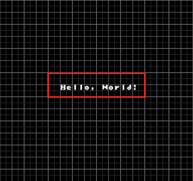
#define ATTR_OFFSET ((TEXT_Y / 4) * (NUM_COLS / 4) + (TEXT_X / 4))Looking at our nametable, we can see that our entire “Hello, World!” text is contained by four of these 32px × 32px areas, so we’ll only need to set four bytes in the attribute table.
Each of these bytes is composed of four sets of two bits, each representing a palette index (0-3) for a 16x16 area of the background. The least significant (rightmost) pair of bits corresponds to the top-left 16x16 area, the next two the top-right, followed by the bottom-left and finally the bottom-right for the most significant pair of bits. Let’s say we want to set the colors for this 32x32 area so that the “ll” is green (palette 1) and the “o,” is yellow (palette 2):

We would set its byte in the attribute table to 0x90, or 0b10010000.
The two least significant pairs are both 00, or palette 0 (which we set to red), though this doesn’t really matter as those correspond to the top-left and top-right tiles which are blank (i.e. just the background color).
The next two pairs are 01 and 10 (palletes 1 and 2, respectively), which gives us the colors we want in the bottom-left and bottom-right tiles.
In our data.h we’re actually going to define ATTRIBUTES to contain three different sets of four bytes each—one set for each of our three colorschemes that we’ll rotate between.
uint8_t const ATTRIBUTES[] = {
    // layout 1 - 0120123
    0x00, // 00 00 00 00 or 0 0
          //                0 0
    0x90, // 10 01 00 00 or 0 0
          //                1 2
    0x40, // 01 00 00 00 or 0 0
          //                0 1
    0xe0, // 11 10 00 00 or 0 0
          //                2 3
…
Pushing to the PPU
Now that we’ve got everything we need, we just have to push it to the PPU. Since we’re going to be writing chunks of memory to the PPU fairly often, let’s create a helper function. As we’re going to be calling it very frequently, instead of sending the parameters via the stack, we’ll use variables in faster zero page RAM:
uintptr_t       ppu_addr;      // destination PPU address
uint8_t const * ppu_data;      // pointer to data to copy to PPU
uint8_t         ppu_data_size; // # of bytes to copy to PPU
Our implementation will write the destination address to PPU_ADDRESS in two bytes (most significant first), and then write ppu_data_size bytes of data starting at ppu_data to PPU_DATA:
void WritePPU() {
    PPU_ADDRESS = (uint8_t)(ppu_addr >> 8);
    PPU_ADDRESS = (uint8_t)(ppu_addr);
    for ( i = 0; i < ppu_data_size; ++i ) {
        PPU_DATA = ppu_data[i];
    }
}
Now we can very easily write all the data we need to render the first frame of our ROM to the PPU:
// write palettes
ppu_addr = PPU_PALETTE;
ppu_data = PALETTES;
ppu_data_size = sizeof(PALETTES);
WritePPU();

// write background tiles
ppu_addr = PPU_NAMETABLE_0 + TEXT_OFFSET;
ppu_data = (uint8_t const *) TEXT;
ppu_data_size = sizeof(TEXT);
WritePPU();

// write attributes
ppu_addr = PPU_ATTRIB_TABLE_0 + ATTR_OFFSET;
ppu_data = ATTRIBUTES;
ppu_data_size = ATTR_SIZE;
WritePPU();
At this point we can reset the scroll position and tell the PPU to start rendering (and enable NMIs).
We’ve encapsulated this in the ResetScroll and EnablePPU utility functions for better readability and reusability.
Making it Move
Once we’ve rendered the first frame, all we have to change in subsequent frames is the four bytes of the attribute table corresponding to our “Hello, World!” tiles.
This is as easy as setting the ppu_data parameter to some offset within ATTRIBUTES before invoking WritePPU.
Twice every second (i.e. every FRAMES_PER_SEC / 2 frames), we’ll rotate the attr_offset between the three layouts we’ve defined in ATTRIBUTES (then reset the scrolling position and frame count) to give us the rotating color effect:
attr_offset += ATTR_SIZE;
if (attr_offset == sizeof(ATTRIBUTES)) {
    attr_offset = 0;
}

ResetScroll();
FrameCount = 0;
And that’s it!
An Introduction to Vertical Blanking
It’s actually very important that we only write data to the PPU when it’s not busy, or else we’ll end up with all kinds of weird screen artifacts.
Before we invoke EnablePPU, we can do all the writing we want as we’re not rendering the screen yet.
Once the PPU is pushing pixels to the screen, however, we have to be careful that we’re only sending data during a short idle time between frames called vertical blanking (often abbreviated as vblank).
The PPU generates an NMI when it enters vblank so we can be notified when it’s safe to write data.
The PPU spends the vast majority of its time busy, therefore vblank is actually a very, very short period of time (roughly 2200 CPU cycles), so we have to make the most of it.
As the PPU runs in parallel to the CPU, vblank can end long before our NMI handler code completes—it’s a race to write everything we need before time runs out.
Fortunately, we’re only copying four bytes at most during vblank for our simple ROM, so we have plenty of time, though we still write those bytes immediately after vblank starts (i.e. our FrameCount changes) and save the offset rotating for afterwards.
When we move on to more complicated ROMs we’ll explore more sophisticated NMI handlers and buffering techniques that make the best use of vblank time.
Next Time
In the next post, we’ll add some sprites to our screen and use the controller to move them around.